![]()
|
|
||
|
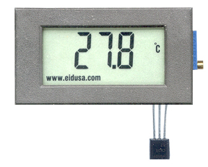
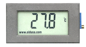
This kit allows you to measure degrees C. It will display on a LCD display (3.5 Digits)
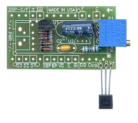
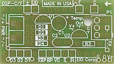
Model A
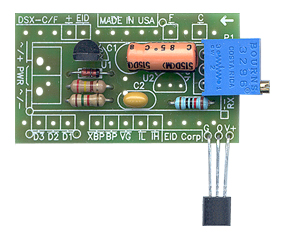
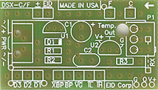
Model B
Kit Model A Includes:
Kit Model B Includes:
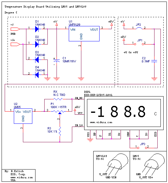
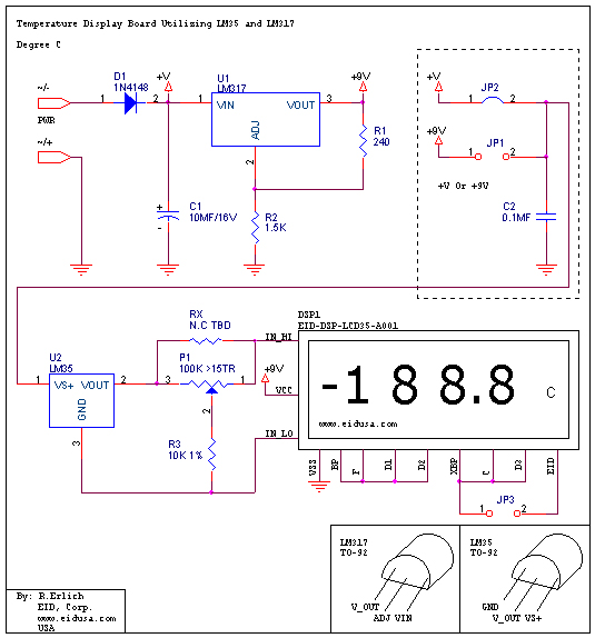
Schematic:
Model A
Model B
This kit utilizing EID 3.5 digit voltmeter display to show very accurate temperature (degrees C) readings using only few external components.
The temperature reading obtains from the LM35 (solid state temperature transducer) in a form of voltage, 1mV per degree Centigrade. The device (LM35) output is linearly proportional to their ambient temperature. For example at room temperature 25 degrees Centigrade the output voltage is 250mV DC. According to the specification (National Semiconductor TM) the device provide typical accuracy of +/-0.25 degree C at room temperature, and +/-0.75 degree Centigrade at full operating temperature rang of -55 to 150C.
Note, even thought the device is specified to operate below 0 degree Centigrade., this kit shows temperature range of 0-60 Degrees Centigrade. This due to the display operation temperature limitations. To obtain higher temperature readings 0-150C use extension wire between the device and the board. Be advise you should compensate the lost of wire voltage via P1.
The board is power of 11-16V DC or AC. The diodes bridge D1-D4 (model A only), together with the capacitor C1, will convert input AC voltage to DC Voltage (See above kit drawing model A). Additionally, the diode bridge ensures that the polarity of the bridge output remains the same regardless of the input voltage polarity. It's what we call "dummy-proof." Let's say, for example, the board is powered by a 12V car battery, the output polarity remains the same no matter how you connect the power to the board's diodes bridge.
The
other side of the diodes bridge drives the voltage regulator U1 (regulator). Regulators usually
having three legs, it converts
varying input voltages and produces a constant regulated output
voltage. They are available in a variety of outputs. The most common part numbers
of the regulator starts with the numbers 78 or 79, and finish
with two digits indicating the output voltage. The number 78
represents positive voltage, and 79 a negative one. The 78XX series
of voltage regulators are designed for positive input. And the
79XX series is designed for negative input. The LM78XX series typically has the ability to drive currents up to 1A.
Application such as this, required less then 150mA, 78LXX can be used.
Therefore, we used the 78L09 as regulator to power this board. As mentioned
above, the component has three legs: Input leg which can hold up to
36VDC (we recommend not to exceed 24V), Common leg (GND) and an output leg with the regulator's
voltage. For maximum voltage regulation, adding capacitor C2 in parallel between the common leg and the output is usually
recommended. C2 a 0.1MF capacitor is used. This eliminates any high frequency AC
voltage that could otherwise combine with the output voltage.
In model B, we substitute the diode bridge and the 78L08 regulator with adjustable regulator Lm317. Together with two resistor R1 and R2 provide regulated output voltage of about 9VDC.
Calculating the LM317 output voltage:
V_LM317 = 1.25V + (1.25V/R1) * 1.5K = 9.0625V
Finally, since the sensor output can generate voltage up to 1.5V at 150C, the sensor output voltage connected to the display via the voltage divider R3 and P1 combination. This will insure 10:1 voltage ratio needed to drive the displays input of 0-200mV.
|
||
|
Description and SKU# |
Price |
Picture |
|
LCD Deg. C display Kit model A EID-K-TEMP-LCD-35A-ASM Fully assembled EID-K-TEMP-LCD-35A-KIT Kit |
29.00 22.95 |
|
|
EID-K-TEMP-LCD-35A-PCB PCB Only |
9.99 |
|
|
LCD Deg. C display Kit model B EID-K-TEMP-LCD-35B-ASM Fully assembled EID-K-TEMP-LCD-35B-KIT Kit |
26.00 19.95 |
|
|
EID-K-TEMP-LCD-35B-PCB PCB Only |
9.99 |
|
|
|
||