![]()
|
|
||
|
9 Voltage Regulator Kit is an Electronics board that allows you to connect 11 to 24V AC or DC on one side of the board and get 9V DC regulated on the other side. Every lab should have a few of these boards handy. The boards will allow you to easily power all your CMOS, components The Terminal Block TB connector is included and makes it easy to use.
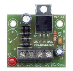
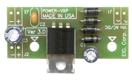
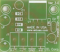
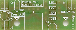
There are two models, A and B. The main difference between the boards is that model A has a power indicator utilizing Light Emitter Diode (LED) L1. Model B doesn't.
Model A Model B
Basic operation of the voltage regulator board:
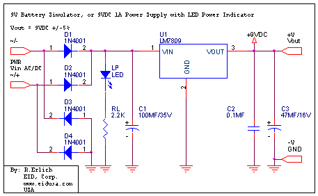
The diodes bridge D1-D4, together with the capacitor C1, will convert input AC voltage to DC Voltage (See below kit drawing). Additionally, the diode bridge ensures that the polarity of the bridge output remains the same regardless of the input voltage polarity. It's what we call "dummy-proof." Let's say, for example, the board is powered by a 12V car battery, the output polarity remains the same no matter how you connect the power to the board's diodes bridge.
The
other side of the diodes bridge drives the voltage regulator U1.
The voltage regulator is the main component of this kit (regulator). Usually
having three legs, it converts
varying input voltages and produces a constant regulated output
voltage. They are available in a variety of outputs. The most common part numbers
of the regulator starts with the numbers 78 or 79, and finish
with two digits indicating the output voltage. The number 78
represents positive voltage, and 79 a negative one. The 78XX series
of voltage regulators are designed for positive input. And the
79XX series is designed for negative input. The LM78XX series typically has the ability to drive currents up to 1A.
Application requirements up to 150mA, 78LXX can be used. As mentioned
above, the component has three legs: Input leg which can hold up to
36VDC (we recommend not to exceed 24V), Common leg (GND) and an output leg with the regulator's
voltage. For maximum voltage regulation, adding capacitors C2
and C3 in parallel between the common leg and the output is usually
recommended. C2 a 0.1MF capacitor is used. This eliminates any high frequency AC
voltage that could otherwise combine with the output voltage.
The LED, see model A below, will indicate that there is voltage after the diodes bridge. The 2.2K Ohms resistor RL determines the LED's brightness and limits the current flow through the LED. To get more lumination (light) from the LEDs, use smaller resistor. Please be advised you should never exceed the LED maximum current limitations. Doing so will result in burning the LED. You should follow the following basic rules: Standard LED will operate on 8 to 20mA and the voltage developed on the LED is about 1.6VDC, therefore:
R_Led
= (V_after_bridge – V_LED) / 20mA =
Again, we recommend that you use slightly a larger resistor to ensure that the current via the LED will not exceed 20mA. Remember, 20mA is generally the maximum current, and typically the LED glows nicely from about 9mA.
Final Note: As a general rule the input voltage should be limited to 2 to 3 volts above the output voltage. The LM78XX series can handle up to 36 volts input, be advised that the power difference between the input and output appears as heat. If the input voltage is unnecessarily high, the regulator will overheat. Unless sufficient heat dissipation is provided through heat sinking, the regulator will shut down.
Kit Includes:
Schematic:
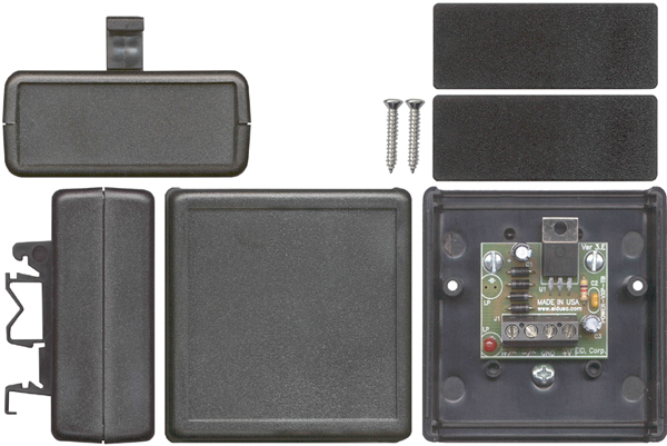
Mounting enclosure and Din Rail clip (options)
Shown above Model A, with LED power indicator mounted in EID-1593KBK
Note: Use heat-sink (if needed). Additionally, Please be advised wires and transformer are sold as options
For our line of transformers click Here
|
||
|
Description and SKU# |
Price |
Picture |
|
9VDC PS, Input up to 24V DC output +9V /1A with LED power indicator. (model A) EID-K-VRG-09VD-L1-ASM Fully assembled EID-K-VRG-09VD-L1-KIT Kit
|
27.39
18.99 |
|
|
EID-K-VRG-XXVD-L1-PCB PCB Only |
9.99 |
|
|
9VDC PS, Input up to 24V DC output +9V /1A (model B) EID-K-VRG-09VD-L2-ASM Fully assembled EID-K-VRG-09VD-L2-KIT Kit
|
24.00
15.99 |
|
|
EID-K-VRG-XXVD-L2-PCB PCB Only |
7.95 |
|
|
EID-K-VRG-XXVD-L2-PCB PCB Only |
7.95 |
|
|
Modified Black enclosure EID-K-1593KBK |
6.97 |
|
|
EID-1427DINCLIP Din Rail Clip |
4.24 |
|
|
|
||