![]()
|
|
||
|
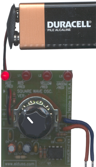
MEET WAVER, the easy 4 frequency square wave sequence generator kit.
The kit is designed to generate the following frequencies: 1HZ, 10HZ, 100HZ, 1KHZ. However, give us a call if you'd like your kit(s) to be modified for other frequencies. Do It Yourself (DIY) and enjoy your kit!
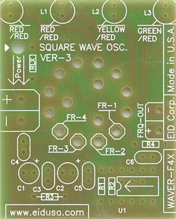
Shown above configured to 1 Hz, 10Hz, 100Hz and 1KHz output. Wires, knob and 9V battery are options
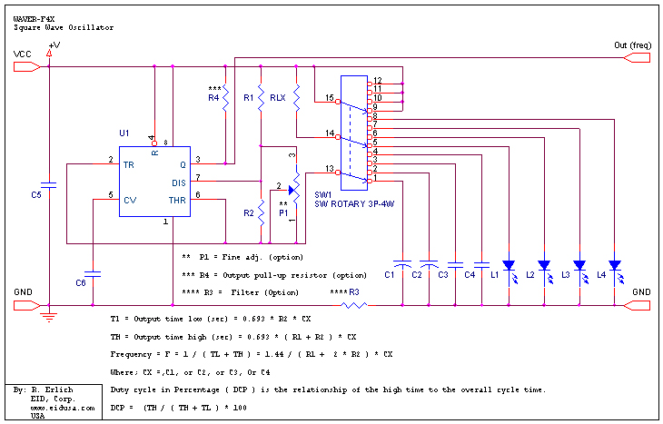
The kit use the timer 555 Integrated Circuit (IC) configured as an Astable circuit, the output (pin 3) is continually switches between the high and low states without any intervention from the user, producing a square wave voltage form. An Astable has no stable state--therefore the name "Astable.”
Most basic and common use of the Astable mode is to flash LED, and 'clock' pulse for other digital ICs and circuits.
As you can see from the schematics below, the resistor (R1, R2), and the capacitor (C1 to C5) values are unspecified. The values of these components determine the frequency and duty cycle of the Astable circuit.
Where;
R1= 3.9 [K Ohms] and R2 = 68 [K Ohms], 1/4W 5% resistors
So if you like 10 [KHz] output frequency, simply substitute C4 with 0.001 [MF]. As you probably gusseted for 100 [KHz] substitute C4 with 0.0001 [MF] = 100 [pF], Since C4=1.44/{(R1+2*R2)*F}=102*10EXP-12=102pF standard capacitor of 100pF will be fine.
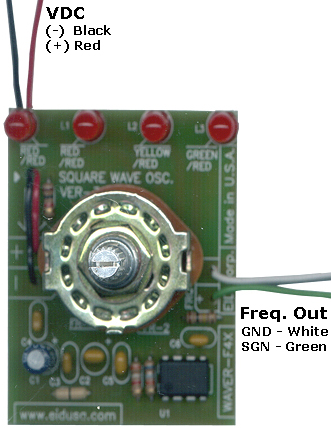
Shown above configured to 10Hz, 100Hz, 1KHz and 10KHz output (wires are options)
When higher accuracy is required, you can add P1 to the board (100K trimmer will do), and adjust the output for the exact frequency you needed. The PCB board provided for this option on the soldering side (3 soldering holes/pads) located under U1.
Capacitor values note:
Formulas:
1. Time High in seconds positive output TH = 0.693 * (R1 + R2) * CX
2. Time Low in seconds negative output TH = 0.693 * R2 * CX
3. Since F = 1/T and T=TH+TL
4. Frequency = 1.44 / ((R1 + R2 + R2) * C)
Finally, the Duty Cycle Percentage (DCP) is the relationship of the high time to (divided by) the overall cycle time =TH/T and is derived by the formula:
5. DCP = (TH / (TH + TL) * 100
|
||
|
Schematic
|
||
|
|
||
|
Description and SKU# |
Price |
Picture |
|
WAVER-F4X Kit EID-K-WAVER-F4X-ASM Fully assembled EID-K-WAVER-F4X-KIT Kit |
36.00 28.95 |
|
|
EID-K-WAVER-F4X-PCB PCB Only |
12.99 |
|
|
|
||