![]()
|
|
||
|
MEET LEVELER, Battery (voltage changes) level indicator via 3 or 4 LEDs kit, ideal to monitor batteries voltage level for those who build "Green-House" power utilizing batteries, windmill, and solar panels!
Our LEVELER - L3 and LEVELER - L4 kit has many applications; One will be able to monitor the level of their RV, car, or solar panels voltage level via front mounted 3 or 4 bright LEDs. Every car, tractor, or boat should have one. The unique small design will allow you to mount it almost anywhere. Operate it with 6V, 9V battery, 12V car battery, four 1.5V batteries, or via one of our battery simulator kits. The alternative uses are endless. It’s designed for the beginner as well as the expert. Please drop us a line at sales@eidusa.com and let us know how you and your kids use your LEVELERS!
When used as car-battery-monitor, it provides early warning of battery problems. Ideal to prevent flat batteries and other embarrassing incidents on your car, recreational vehicle (RV), tractor, or boat. The board gives visual indication via front mounted LEDs of current battery voltage. YEP--be in the green (green LEDs) and drive safe. Finally, connect the board to the car battery via front mounted terminal block is a snap.
When configuring the kits using three LEDs, Green LED indicating "Good" Yellow LED for "Weak" and Red LED for "High". Adding the 4th LED L4 to indicate extreme high voltage condition.
The LEVELER-L3/L4 heart is the PIC micro-processor Integrated Circuit (IC) PIC12F675 (4MHZ version) by Microchip, Corp.
This kit is an educational electronics kit that allows one to customize the LED level and its corresponding voltage hysteresis and more by changing the Assembler code (software) provided (YES .ASM and .HEX are AS-IS and FREE!).
One can program the PIC using PIC-KIT2 by Microchip Corporation directly from personal computer (PC) via Universal Serial Port (USB).
Note: The PIC 12F675 IC is 8 pin DIP, 14bit type Micro-processor with 4 Analog to Digital port and 6 I/O. Click here to download the the PIC 12F675 chip data-sheet.
Do It Yourself (DIY) Software driven PIC (12F675) micro-processor base kit, and have a blast!
|
||
|
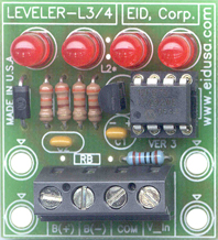
Shown above configure with 4 LEDs (program to 4 level indications) and 0-5V DC input (RA = 10K, 0.25W, 1%)
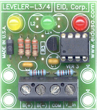
Shown above configure with 3 LEDs and 0-10V DC input (RA = RB =10K, 0.25W, 1%)
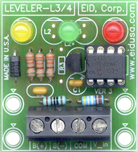
Shown above configure with 3 LEDs and 0-30V DC input (RA = 4.99K, 0.25W, 1% and RB = 1K, 0.25W, 1%)
|
||
|
Kit Includes:
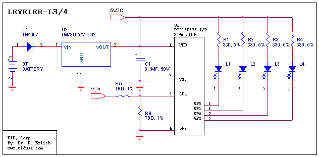
Schematic:
|
||
|
MEET LEVELER – Our alternating battery monitoring LEDs kit. The kit is based on “PIC micro-processor PIC12F675. Using software code to control (turn ‘on’ and ‘off’) voltage level the corresponding to the LED. This basic kit can work with many conventional color LEDs to indicate the voltage level such as Green, Yellow or Red etc.
The 330 Ohms resistor determines the LED's brightness and limits the current flow to about 10mA when running with 9V battery. Standard LED will operate on 10-20mA and the voltage developed on the LED is about 1.6VDC, therefore:
R_Led
= (V_Bat – V_CE – V_LED) / 20mA =
The LEVELER is determined what LED to light base on the input voltage (PIC pin #4) this voltage will change the voltage on the ADC between 0-5V. The voltage then reads back to the micro-processor and the software converts this value and light the right LED. The LEVELER voltage hysteresis is determined by the software
Finally, the only hardware change will be determined by the Voltage divider RA and RB to insure maximum of 0-5V input to the PIC analog to digital converter input (pin #4). Use the follow formula/example:
V_In_board_max = Maximum board input voltage level, for example 30V DC to monitor 24V battery.
V_In_max = Maximum PIC's analog to digital input voltage level 5V DC.
RA and RB are the corresponding voltage divider 1% resistors.
Where RB = 1K, 1%
V_In_max = V_In_board_max * ( RA / (RA +RB)), 5VDC = 30VDC ( RA / ( RA + X )) ==> RA = 4.99K, 1%
SKU/ P# Note: XXX = Input level. where; 0-5V is standard, XXX = 010 for 0-10V input and XXX =030 for 0-30V input
|
||
|
Description and SKU# |
Price |
Picture |
|
LEVELER L3 Kit EID-K-LEV-ELER-L3-XXX-ASM (Fully assembled) |
29.43 |
|
|
LEVELER L3 Kit EID-K-LEV-ELER-L3-XXX-KIT Kit Only |
24.93 |
|
|
LEVELER L4 KIT EID-K-LEV-ELER-L4-XXX-ASM (Fully assembled) |
29.73 |
|
|
LEVELER L4 KIT EID-K-LEV-ELER-L4-XXX-KIT Kit Only |
25.20 |
|
|
EID-K-LEV-ELER-LX-PCB PCB Only |
12.87 |
|
|
|
||