![]()
|
|
||
|
|
||
|
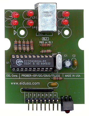
INTERFACER – EUSB6. EID's EUSB to 6 I/O pins and 6 LEDs interface board.
The INTERFACER-EUSB6 is a universal USB to I/O board (6 I/O read or write) that can be used to control Input and Output pins (I/O) directly from your Personal Computer (PC). If used properly, it will eliminate the need for expensive boards and programming skills, otherwise needed to carry out the same tasks.
The circuit board features 6 LEDs and 6 I/O pins fully controlled via the PC via the EID's universal serial bus (EUSB). It powered via 5V directly from your PC, indicated by additional front mounted LED.
This unique board design provides you with ability to wire your wires easily via front mounted connector (6 I/O pins and two pins for +5VDC and GND). Additionally, you will be able to monitor the 6 I/O directly from the PC.
The fully software controlled board I/O pins can sink up to 16 levels (0 to 15) of current.
No need for external Power supply! The board is powered directly from your PC.
The INTERFACER-EUSB6 is easy to install, setup and operate. If you want to do professional software control related USB functions, the INTERFACER-EUSB6 offers the features you need. The uses are endless.
|
INTERFACER-EUSB6
|
|
|
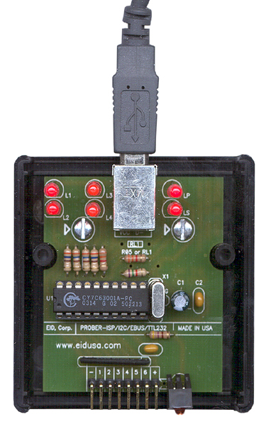
Mounting the board
Mounted easily via two 0.125" mounting holes.
Shown above mounted in plastic enclosure (EID-1593 series).
Please note: EUSB wire (USB cable), plastic enclosure and mounting screws are sold separately (for demonstration only).
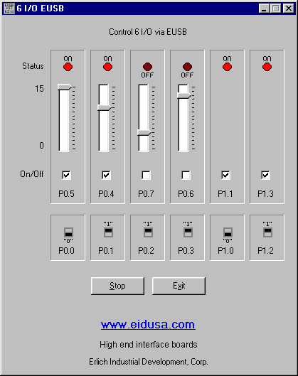
Software
Free demo software (see above screen shot) allows you to fully control the 6 on board LEDs. Turn them on and off, or simply control their brightness (4 of 6) via on screen 16-levels slide-like switch. The software also provides you with the means to test your switches. When the switch is pressed (short to ground) the corresponding "on screen switch" will change to "0". Just release it, and it will change back to "1". No need for external pull-up resistors! They are provided (set) internally on-chip via our unique firmware (provided free with your kit). The Cypress USB IC (CY7C63001) has built-in pull-up software controlled resistors. So when you read P0.0 - P0.3 and P1.0, P1.2 I/O pins you will get "1". When you short any of them to ground, your software will give you "0".
All you need to do is to plug-in the board via EUSB cable to your PC, run the free demo software, and viola, you can control the LEDs and read the switch positions.
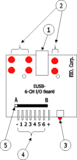
Drawing information
1. EUSB connector (connect your cable between the connector and your PC) 2. LED I/O Status 3. LED power indicator 4. Connector (Pin 1 GND, Pin 2 to 7 I/O-1 to I/O 6, Pin 8 +5VDC) 5. Pull up external resistor mounted B direction, Or pull down resistor mounted in A direction.
INTERFACER – EUSB6 Features
Specifications, Electrical Characteristics - Ta=+25°C
Electrical schematic
|
||
|
Software and schematics note
1. FREE pre-install EUSB firmware.
2. LEDs Controlled via the following Port's and bit-number:
3. I/Os connector's pin controlled via the following Port's and bit-number:
EUSB Basics
The EUSB (EID’s Universal Serial Bus) provides a new way of interfacing low speed peripherals to personal computers. Adding I/O pin and/or Analog to digital converter (ADC) integrated circuit (IC) to your application on the PC via a EUSB interface is now easier than ever.
EID’s “engineering and applied science group” develop basic electronics kits which include on board pre-installed EUSB firmware. Just link your software application with our DLL, enter a few lines of code and you're done. EID’s EUSB support the USB protocol (see www.usb.org) among others…
EUSB uses a time-shared serial data stream. The PC acts as a master by polling all connected peripherals at regular intervals of one milli-second (1mS). Each peripheral responds by placing its data on the time multiplexed bus at their allocated time within this 1mS frame. An addressing configuration mechanism allows up to 127 devices to be connected to the bus.
EUSB utilizes a four-wire cable structure. Two leases are used for differential data, the other two are used for power +5 Volt DC and Ground (GND). See below connector drawings.
EID's
board side
The
Protocol is very complicated, however, our software
package (DLL + firmware) takes care of it. For general knowledge, all you need to know is that the PC transferred data from the EUSB board is in packet bursts contained within frames separated by 1mS. Low speed devices operate at a rate of 1.5Mbit/s. There are faster rates today i.e 12Mbit/sec, we use the kit to demonstrate interface for industrial and HVAC applications, checking sensors, etc. 1.5Mbit/sec is very fast.
Stop reading here, and go directly to code example -- unless you really want to know more details on the protocol...
EUSB peripherals have to synchronize their outputs to the frame start. The bit rate clock is recovered from the NRZI encoded data stream, see drawings below.
EUSB peripheral may have more than one “endpoint”. Endpoints are different destination registers sharing the same device address. Different endpoints can be used for initializations and control, and for ordinary data transfers. EUSB uses the term “pipe” to denote a data transfer from the PC to a particular endpoint. To increase data rate, a peripheral may occupy more than one pipe at a time.
There are four basic methods of transferring information between a PC and a EUSB peripheral:
Control –Transfer (CNT): Used to send control signals to the peripheral. These have high priority and incorporate inbuilt error protection. It is used for transferring initializations information, but can also be used for general-purpose low speed data transfers. Our kits support control transfers.
Bulk
– Transfer (BT): Used by storage devices to transfer
large amounts of data in a time independent manner. This
is useful for printers, disk drivers etc. This method
has low priority on the bus. Interrupt – Transfer (INT): Used by low speed data peripherals such as mice and keyboards that need to send small amounts of data quickly and periodically to the PC.
Isochronously
– Transfer (IST): Used by peripherals transferring
large amounts of data at a defined data rate, e.g.
soundcards. No error protection is included. The system
must assume that some data may be lost. All of our board using an error protected control link utilizing the low speed bus and guaranteed data rate is limited to 800 bytes per second.
On your personal computer (PC), witch we assuming has support for EUSB via kernel level device drivers in the operating system. Each EUSB peripheral requires a driver of its own “class”. EUSB is a “hot wire” protocol. The PC can also recognize when a peripheral has been plugged or unplugged during normal work, and is able to load or unload the corresponding driver at the same time. This makes EUSB more or less transparent to the user.
Windows includes a EUSB driver for interface EUSB going under the generic name of HID (human interface devices). This allows for our generic boards to be plugged in without having installing a special driver.
The installation procedure is very simple. When the EUSB-kit is plugged in, a polling signal causes Windows to send signals on the EUSB asking for identification. The peripheral responds with its own PID and VID (Product and Vendor IDs). Windows then searches its directories for the correct driver assigned to that particular peripheral. If it cannot find one, it pops up a message requesting the user to install one. The drivers are usually supplied on CD. Once the driver is installed, the application program carries on as normal.
Adding EUSB is a very simple -- our kit uses Cypress devices with enough memory and processing power for all of our flagship boards and kits. EUSB support is provided in the form of firmware subroutines witch we created in pre-download to the chip on the board. All you need to do is to link it into your own code. See code samples and libraries.
No need to create the Product and Vendor description tables. Most of the information here will be provided by the firmware. If needed (for additional cost) we may customized them for your information and needs.
We use a negative number ID that makes our kit boards uniquely recognizable by the operating system in order to load the right driver. Since the standard doesn't include or call for negative ID numbers, we use one for our boards. Our EUSB series of kits are for research and development purposes only! Therefore, if you would like to use them as products -- commercial or other, we strongly recommend that you will obtain (for a fee) your own USB product ID (PID) and vendor ID (VID). See www.usb.org for more details. Doing so, will ensure that your product doesn't interfere with other USB products.
Finally, the EUSB cable can provide some power for the peripheral up to 400mA to be drawn when the peripheral is active, but only 500uA when inactive. This means you have to provide for means of switching the power off while the EUSB is in the suspended state.
|
||
|
Pricing
* Prices, SKU#, P#, specifications, and colors are subject to change without notice. Additional 10% discount with student ID, USA only. Call for OEM pricing.
|
||
|
Description |
SKU # |
Price 1-10 |
|---|---|---|
|
INTERFACER-EUSB6 EUSB to 6 I/O BUS Board |
EID-INTERF-CER-EUSB6-P1 |
$49.00 |
|
EUSB DLL Software (Library only) |
EID-INTERF-CER-EUSBD-SF |
$12.00 |
|
Two Teflon 3/4" long mounting spacers and Four 4-40 1/4" screws. |
EID-INTERF-CER-XX34-4-40 |
$7.99 |
|
Two Teflon 1/2" long mounting spacers and Four 4-40 1/4" screws. |
EID-INTERF-CER-XX12-4-40 |
$6.99 |
|
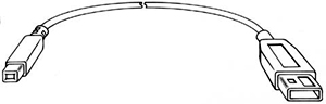
EUSB A to B type cable This cable is used to connect the EUSB (or USB) port to the EUSB peripheral. A male B Male types. EUSB 3' EUSB 6' EUSB 10' EUSB15' |
EID-C-USB-32-930 EID-C-USB-32-931 EID-C-USB-32-932 EID-C-USB-32-933 |
$9.99 $10.99 $11.99 $15.99 |
|
|
||

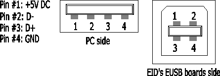
 PC side